Ultrasonic sensor HC-RS04 for robotics applications using VHDL
In this sample, I show how to design the architecture of the ultrasonic sensor for robotics applications. A number represented in the seven segment display correspond to some distance defined in the distant calculation entity.
Finally, it is a part of my complete FPGA course. If you interested in my course or you need help in your projects as freelancer contact me at:
postgraduatecahg@gmail.com
Figure 1. Working principle.
Solution:
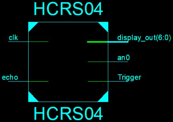
Figure 2. TOP Design.
Figure 3. RTL schematic.
library IEEE;
use IEEE.STD_LOGIC_1164.ALL;
use ieee.std_logic_unsigned.all;
entity HCRS04 is
Port ( clk : in STD_LOGIC;
echo : in STD_LOGIC;
Trigger : out STD_LOGIC;
an0 : out std_logic;
display_out : out STD_LOGIC_VECTOR (6 downto 0));
end HCRS04;
architecture Behavioral of HCRS04 is
COMPONENT TriggerGen
PORT(
clk : IN std_logic;
trigger : OUT std_logic
);
END COMPONENT;
COMPONENT counter
PORT(
clk : IN std_logic;
reset : IN std_logic;
enable : IN std_logic;
q : OUT std_logic_vector(19 downto 0)
);
END COMPONENT;
COMPONENT distance_calculation
PORT(
echo_count : IN std_logic_vector(19 downto 0);
distance : OUT std_logic_vector(3 downto 0)
);
END COMPONENT;
COMPONENT display_decoder
PORT(
distance_in : IN std_logic_vector(3 downto 0);
display_out : OUT std_logic_vector(6 downto 0)
);
END COMPONENT;
signal Trigger_out: std_logic;
signal echo_counter1 : STD_LOGIC_VECTOR (19 downto 0);
signal echo_count : STD_LOGIC_VECTOR (19 downto 0);
signal distance_bits : std_logic_vector(3 downto 0);
begin
Inst_TriggerGen: TriggerGen PORT MAP(
clk,
Trigger_out
);
Inst_counter: counter PORT MAP(
clk,
Trigger_out,
echo,
echo_counter1
);
process(echo) begin
if falling_edge(echo) then
echo_count <= echo_counter1;
end if;
end process;
Inst_distance_calculation: distance_calculation PORT MAP(
echo_count,
distance_bits
);
Inst_display_decoder: display_decoder PORT MAP(
distance_bits,
display_out
);
Trigger <= Trigger_out;
an0 <= '1';
end Behavioral;
---------------------- TriggerGen ----------------------------------
library IEEE;
use IEEE.STD_LOGIC_1164.ALL;
use ieee.std_logic_unsigned.all;
entity TriggerGen is
generic (n: integer :=20);
Port ( clk : in STD_LOGIC;
trigger : out STD_LOGIC);
end TriggerGen;
architecture Behavioral of TriggerGen is
signal tick: std_logic_vector(n-1 downto 0) := (others =>'1');
constant nclks: integer := 750000; --1000000; --it corresponds to 20ms
begin
process (clk) begin
if clk'event and clk = '1' then
if tick < nclks-1 then
tick <= tick + 1;
else
tick <= (others => '0');
end if;
end if;
end process;
trigger <= '1' when (tick < 500) else '0';
end behavioral;
----------------------------- counter -----------------------------
library IEEE;
use IEEE.STD_LOGIC_1164.ALL;
use ieee.std_logic_unsigned.all;
entity counter is
generic (N: integer := 20);
Port ( clk : in STD_LOGIC;
reset : in STD_LOGIC;
enable : in STD_LOGIC;
q : out STD_LOGIC_VECTOR (N-1 downto 0));
end counter;
architecture Behavioral of counter is
signal tick: std_logic_vector(N-1 downto 0);
begin
process (reset, clk, enable) begin
if reset = '1' then
tick <= (others => '0');
elsif clk'event and clk = '1' then
if enable = '1' then
tick <= tick + 1;
end if;
end if;
end process;
q <= tick;
end Behavioral;
------------------------------------ distance_calculation -------
library IEEE;
use IEEE.STD_LOGIC_1164.ALL;
use ieee.std_logic_unsigned.all;
entity distance_calculation is
port(
echo_count : in STD_LOGIC_VECTOR (19 downto 0);
distance : out STD_LOGIC_VECTOR (3 downto 0)
);
end distance_calculation;
architecture Behavioral of distance_calculation is
begin
Distance <="0000" when (echo_count < 2900) else --0cm
"0001" when (echo_count > 2900 and echo_count < 8700) else --3cm
"0010" when (echo_count > 8700 and echo_count < 14500) else --3-5cm
"0011" when (echo_count > 14500 and echo_count < 21750) else --5-7.5cm
"0100" when (echo_count > 21750 and echo_count < 27550) else --7.5-9.5cm
"0101" when (echo_count > 27550 and echo_count < 30450) else --9.5-10.5cm
"0110" when (echo_count > 30450 and echo_count < 33350) else --10.5-11.5cm
"0111" when (echo_count > 33350 and echo_count < 37700) else --11.5-13cm
"1000" when (echo_count > 37700 and echo_count < 40600) else --13-14cm
"1001" when (echo_count > 40600 and echo_count < 46400) else --14-16cm
"1010" when (echo_count > 46400 and echo_count < 49300) else --16-17cm
"1011" when (echo_count > 49300 and echo_count < 52200) else --17-18cm;
"1100" when (echo_count > 52200 and echo_count < 55100) else --18-19cm;
"1101" when (echo_count > 55100 and echo_count <58000) else --19-20cm;
"1110" when (echo_count > 58000 and echo_count < 63800) else --20-22cm;
"1111";--more than 22cm
end Behavioral;
----------------------------- display_decoder ------------------
library IEEE;
use IEEE.STD_LOGIC_1164.ALL;
entity display_decoder is
Port ( distance_in : in STD_LOGIC_VECTOR (3 downto 0);
display_out : out STD_LOGIC_VECTOR (6 downto 0));
end display_decoder;
architecture Behavioral of display_decoder is
begin
display_out <="1000000" when distance_in = "0000" else
"1111001" when distance_in = "0001" else
"0100100" when distance_in = "0010" else
"0110000" when distance_in = "0011" else
"0011001" when distance_in = "0100" else
"0010010" when distance_in = "0101" else
"0000010" when distance_in = "0110" else
"0111000" when distance_in = "0111" else
"0000000" when distance_in = "1000" else
"0011000" when distance_in = "1001" else
"0000110";
end Behavioral;
-------------------------------- Test Bench of All----------------
USE ieee.std_logic_1164.ALL;
ENTITY hcrs04_top IS
END hcrs04_top;
ARCHITECTURE behavior OF hcrs04_top IS
-- Component Declaration for the Unit Under Test (UUT)
COMPONENT HCRS04
PORT(
clk : IN std_logic;
echo : IN std_logic;
Trigger : OUT std_logic;
an0 : OUT std_logic;
display_out : OUT std_logic_vector(6 downto 0)
);
END COMPONENT;
--Inputs
signal clk : std_logic := '0';
signal echo : std_logic := '0';
--Outputs
signal Trigger : std_logic;
signal an0 : std_logic;
signal display_out : std_logic_vector(6 downto 0);
-- Clock period definitions
constant clk_period : time := 20 ns;
BEGIN
-- Instantiate the Unit Under Test (UUT)
uut: HCRS04 PORT MAP (
clk => clk,
echo => echo,
Trigger => Trigger,
an0 => an0,
display_out => display_out
);
-- Clock process definitions
clk_process :process
begin
clk <= '1';
wait for clk_period/2;
clk <= '0';
wait for clk_period/2;
end process;
echo_process :process
begin
echo <= '0';
wait for (clk_period/2)*100000;
echo <= '1';
wait for (clk_period/2)*10000;
echo <= '0';
wait for (clk_period/2)*1600000;
end process;
END;

Figure 4. Test bench simulation.
-------------- UCF file using Nexys II board -----------------------
#clk
NET 'clk' LOC = 'B8';
# HCRS04
NET 'echo' LOC = 'M15' | CLOCK_DEDICATED_ROUTE = FALSE;
NET 'Trigger' LOC = 'L17';
#Display
NET 'display_out(0)' LOC = 'L18';
NET 'display_out(1)' LOC = 'F18';
NET 'display_out(2)' LOC = 'D17';
NET 'display_out(3)' LOC = 'D16';
NET 'display_out(4)' LOC = 'G14';
NET 'display_out(5)' LOC = 'J17';
NET 'display_out(6)' LOC = 'H14';
# Anodo.
NET 'an0' LOC = 'F17';


